


Introduction
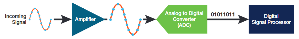
One of the most important functional blocks in a digital oscilloscope is the analog-to-digital converter or ADC. This technical brief explains why ADC resolution (number of bits) has become a more important consideration in oscilloscopes, especially for measuring small signal details.

Many high-precision instruments use high numbers of bits in their ADC's. For example, a precision digital multimeter (DMM) like the Keithley 2002 can make measurements with up to 28 bits. So why has oscilloscope resolution traditionally been lower? Oscilloscopes have traditionally used 8-bit ADCs because oscilloscope ADC technology has prioritized sample rate. 8-bit ADCs can provide high sample rates and therefore excellent time resolution. Even relatively inexpensive oscilloscopes now sample at GS/s. In contrast, the sampling rates of DMMs are much lower - roughly on the order of tens to hundreds of samples per second.
The 8-bit ADC in an oscilloscope provides a good balance between acquisition speed and amplitude accuracy for signals with frequencies in the hundreds and TTL voltage levels on the order of 0 to 5 V. For this type of signal 8-bit resolution is usually sufficient.
However, as we move into new technologies such as IoT devices, mobile devices, and autonomous vehicles that rely on high-speed networks, low interference, and low power consumption, engineers are facing new challenges of validating very small amplitude signals with greater accuracy.
This need to address smaller signal details is driving the need to increase the number of ADC bits, while carefully keeping oscilloscope noise low.
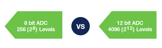
Traditional 8-bit ADCs (ignoring oversampling and postprocessing provide 28 = 256 vertical digitizing levels. This can be too coarse for applications like power supply design which demands higher vertical resolution over relatively high voltage ranges. In contrast, a 12-bit ADC can deliver up to 212 = 4096 vertical digitizing levels for an extremely large increase in vertical resolution (Figure 2).
ASICs at the Heart of Tektronix 12-bit Oscilloscopes
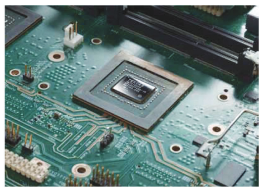
Tektronix new 4 Series, 5 Series, 6 Series MSO oscilloscopes are equipped with 12-bit ADC technology to help you accurately capture tiny signal details. High resolution is delivered by a custom ASIC called the TEK049, which is shown in Figure 3 and is at the heart of every Tektronix 4, 5 and 6 Series MSO (mixed signal oscilloscope). These scopes support high-definition displays, up to 8 FlexChannel® inputs, 12-bit vertical resolution, and up to 16 bits of resolution with oversampling, all thanks to circuitry integrated into the TEK049. It is a highly-integrated mixed signal system on chip (SOC), with 400 million transistors and 2 billion connections, consisting of four ADCs and signal processing. The ADCs can achieve sample rates up to 25 GS/s.
A Measurement Case Study: Power Supply Switching Measurements
In this example, we are evaluating a switching section in a power supply. This measurement is challenging because we want to look at the periodicity of ringing on a rather large switching signal. The oscillations are relatively small, compared to the amplitude of the switching signal.
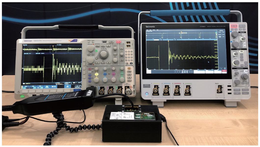
Figure 4 shows the same test using oscilloscopes with different vertical resolutions. The switching circuit rings after each cycle and the goal is to examine the oscillations. To see the entire switching cycle, the vertical scale must be set to around 1 V/div to fit the signal into the 10 divisions of the display.
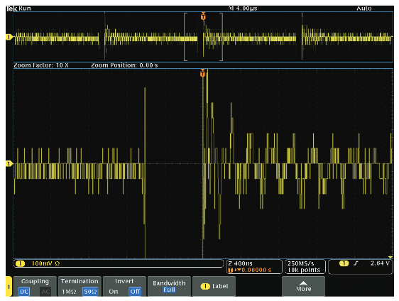
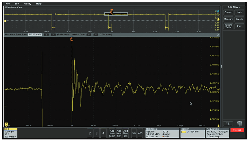
Measurement Results
Figures 5 and 6 show the two oscilloscopes under the same conditions: (250 MSa/s sampling rate, 10 k samples, 1 V per division). The same IsoVu optically isolated voltage probe was used on both instruments, to virtually eliminate the effects of probe noise. You can see that with the 8-bit oscilloscope the results with high zoom factor are limited, because significant quantization steps appear, making it difficult to analyze the oscillations. However, the 12-bit oscilloscope clearly shows the oscillations at a comparable zoom setting.
The new 4, 5 and 6 Series MSOs offer 12-bit vertical resolution, making it possible to see more signal detail and make more accurate measurements.
For more information on the techniques used to achieve higher-resolution acquisition details download the white paper Achieve Higher Vertical Resolution for More Precise Measurements.
Find more valuable resources at TEK.COM
Copyright © Tektronix. All rights reserved. Tektronix products are covered by U.S. and foreign patents, issued and pending. Information in this publication supersedes that in all previously published material. Specification and price change privileges reserved. TEKTRONIX and TEK are registered trademarks of Tektronix, Inc. All other trade names referenced are the service marks, trademarks or registered trademarks of their respective companies.
1/20 48W-61643-0