

The trigger features and controls on modern oscilloscopes have come a long way since the introduction of triggered sweep oscilloscopes 65 years ago. These controls have evolved from simple edge triggering on a rising or falling edge of a signal with some possible filtering to very sophisticated advanced functions that can trigger on glitches, runts, specific widths, logical combinations of signals and digital data patterns.
With multi-level sequential triggering, literally thousands of combinations of trigger settings can be devised to specifically target your signal of interest. In the midst of this trigger sophistication and complexity, lays a simple trigger control that is often overlooked, and even more often, misunderstood – the Trigger Holdoff control.
Trigger Holdoff functionality first appeared in the Tektronix lineup with the 485 which was introduced in 1972. While this feature exists in modern digital scopes today, it makes sense to describe the concept of trigger holdoff in the context of a traditional analog oscilloscope’s triggered sweep functionality.

Analog Oscilloscope Triggered Sweep
In an analog oscilloscope, the trace is formed by sweeping an electron beam across the face of the CRT which creates a glowing trace in the phosphor via a linear voltage ramp applied to the horizontal deflection plates inside the CRT.
The trigger circuit inside the scope is what initiates the sweep. When the scope gets triggered, it starts the horizontal ramp voltage which sends the beam across the screen. When the sweep hits the right side of the screen, the scope then blanks the beam and returns the sweep voltage back to the starting point, thus moving the beam back to the left of the screen. This process is called “retrace.” Once the sweep and the retrace are completed, the scope re-arms the trigger circuit and waits for another trigger event to start the process over again.
Trigger Holdoff Operation
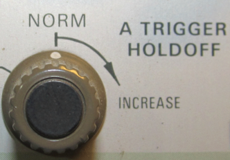
Once the trigger starts the process described above, the trigger circuit will ignore any additional trigger events, and is “held off” until the sweep and the retrace are completed. Then, the trigger circuit is re-armed and ready to initiate another sweep/retrace when a valid trigger event occurs. The Trigger Holdoff control quite simply provides a means to add an additional, user-defined delay to the re-arming of the trigger circuit, beyond the end of the sweep/retrace period. This gives the user some control over how rapidly, or how often, the oscilloscope can be triggered.
In the figures below, the upper trace represents the sweep voltage in an analog scope, and the lower trace represents the trace blanking signal. This shows that the trace is blanked during the retrace and tail end of the holdoff period. The figure on the left shows the minimum holdoff time, where the trigger is re-armed very quickly after the retrace. The figure on the right shows the result of increasing the Trigger Holdoff control.
 (NXPowerLite).jpg")
In modern digital scopes, the trigger and acquisition model is a bit different than that of the analog scope described above. However, the end result of the Trigger Holdoff function is the same.
In digital scopes, the input signals are essentially being sampled continuously. The signals are put into memory and sent to the trigger system which examines them for events that meet the trigger criteria. When this occurs, the user-requested acquisition is completed and displayed. Because of the continuous sampled nature of the system, both pre-trigger and post-trigger data is saved. This is a major advantage of digital scopes over their analog predecessors.
The Trigger Holdoff function has the same function on digital scopes as it does on analog scopes: It tells the trigger circuit how long to ignore candidate trigger events after a valid trigger event is found.
Uses of Trigger Holdoff
Trigger Holdoff can be of great assistance in observing and analyzing modern signals that are often packetized, or bursty in nature. This applies to everything from simple inter-chip bus signals such as SPI or I2C, to RF signals like Bluetooth, Zigbee, WLAN and cellular. These short duration signal bursts are used for a variety of reasons including power reduction, media sharing, and time division multiplexing.
Packetized signals can present a problem when it comes to triggering on them in an oscilloscope since they can lead to unstable, inconsistent triggering. This is because the trigger circuit can re-arm itself in the middle of a burst of data/signal rather than at the beginning. The resulting scope display will then be a series of overlapped acquisitions that are difficult to decipher because the packets acquired are all misaligned.
Often these packets have some structure to them such as a defined length or a defined repetition interval. By simply using the Trigger Holdoff, the oscilloscope can often reliably re-arm the trigger circuit in the “gap” between the packets or bursts, so that all bursts of data are triggered and acquired at the beginning, not somewhere in the middle. This makes the capture of these signals very easy.
The figures below were obtained with the same input signal, a 350uS bursted sine wave with a 500uS gap between the bursts. Without using Trigger Holdoff (left), the scope is sometimes triggered at the beginning of the burst, and sometimes triggered near the end of the burst, resulting in an overlapped display that is difficult to interpret. By properly adjusting the Trigger Holdoff (right) so that the trigger is re-armed during the gap between the bursts, a stable non-overlapped trace results.
 (NXPowerLite).jpg")
Summary
The Trigger Holdoff feature was first introduced more than 40 years ago, but is as relevant today as it was then. It is a feature that is rarely discussed, and often misunderstood, but can prove to be extremely valuable to reliably trigger on tricky signals. This simple control can be used to reliably trigger on seemingly difficult or complex signals – yesterday, today, and tomorrow. Take the time to get to know your Trigger Holdoff control; you’ll be glad you did.