

In the course of our careers, we don’t get many chances to be trail blazers. With PAM4 design and test techniques still in flux and different labs using different techniques, it’s the perfect time to become a PAM4 expert.
Tektronix has just released the first, complete, up to the second, PAM4 application note: “PAM4 Signaling in High Speed Serial Technology: Test, Analysis, and Debug.” It explains what PAM4 is, the problems it solves, the problems it introduces and what to expect going forward. They even promise to keep it up to date.
Standards Today
So far, just one PAM4 standard has been released: 100GBASE-KP4, 100 Gigabit Ethernet, which is covered in IEEE 802.3bj. At 13.6 GBd (i.e., 27.2 Gb/s), it hasn’t been widely adopted because good old NRZ works okay at these rates. But there’s no getting around PAM4 above 50 Gb/s. The new PAM4 App Note comes from the experience of the Tektronix engineers who are working on PAM4 technology and contributing to 400G standards like 400 Gigabit Ethernet, 56G OIF-CEI, and all the rest.
How did we get here?
The problem is the frequency response of transmission channels. In the good old days, we could think of digital signals as though they were DC signals that turned on and off with logic-highs and logic-lows. But data rates increased and we had to think of high speed signals as microwaves propagating along waveguide traces on printed circuit boards. Conducting traces on circuits and backplanes are all twists and turns, skin effect and dispersion with loss of 70+ dB around 25 GHz. The resulting ISI (inter-symbol interference) shuts eye diagrams.
We got away with baseband-looking NRZ by conditioning the signal at both the transmitter with FFE (feed forward equalization) and at the receiver with CTLE (continuous time linear equalization) and DFE (decision feedback equalization) but these techniques run out of steam somewhere between 25 and 50 Gb/s.
Comparing PAM4 and PAM2-NRZ
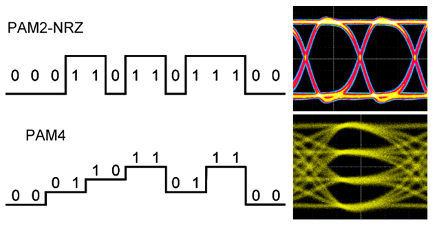
By coding two bits per symbol, PAM4 transmits twice as much data as PAM2-NRZ at the same symbol rate, the same baud. You’ll notice that I put a “PAM2” prefix on good old NRZ. The thing is, the digital-looking NRZ signals are more accurately described as 2-level pulse amplitude modulation, PAM2, than non-return to zero.
The figures below compare PAM4 and PAM2-NRZ signaling.


Comparison of PAM4 and PAM2
PAM4 has sixteen different bit transitions compared to four, six rising/falling edges compared to two, and three eyes enclosed in the voltage swing and unit interval where we used to have one. PAM4 suffers at least three times the signal-to-noise problems that PAM2-NRZ faces. One symbol error can cause two bit errors, especially if jitter is the culprit. Along with these complications, we now have to think about the weakest link in the three eye chain; the BER (bit error ratio) will only be as good as the worst eye.
We will bring every tool that we have to the PAM4 lab bench. Differential signaling, embedded clocking and clock recovery, and equalization at both the transmitter and receiver. Differential signaling doesn’t change, clock recovery is trickier with edges that aren’t as distinct, transmitter equalization—both multi-tap FFE and simple de-emphasis—is complicated by the four symbol levels, CTLE receiver equalization doesn’t change, but DFEs have four decisions to feed back.
Three eyes also means three voltage slicers. The first adopters will use common timing for the three slicers; later technologies might have independent timing. The relative proportions of the three eyes introduces a whole new category of linearity issues. Right now, engineers in different labs use their own techniques to measure timing and voltage nonlinearities. As the technology evolves new test techniques will converge.
PAM4 might seem to create as many problems as it solves, but the standards bodies have granted us a boon: by incorporating FEC (forward error correction) the BER requirement has been relaxed by a factor of 100,000. Instead of designing and testing to BER better than 10-12 or 10-15, PAM4 designs have to meet BER < 10-6. Relaxing the PHY layer BER requirement gives one gargantuan test advantage, and we’ll need it.
To test PAM2-NRZ systems down to BERs of 10-12 or lower, we either had to perform tests that took 20 minutes to an hour or extrapolate faster measurements down deep into the noise. Where interpolation is a perfectly reasonable technique for estimating a value between two measurements, extrapolation is a leap off the edge of a measurement’s reliability. By requiring BER < 10-6, we can measure the full impact of noise and jitter in a fraction of a minute with a BERT (bit error ratio testers) or an oscilloscope.
Understanding PAM4
The transition from PAM2-NRZ to PAM4 is a fundamental shift in our industry that we’ll all need to understand, better sooner than later. Fortunately, it’s all spelled out in the “PAM4 Signaling in High Speed Serial Technology: Test, Analysis, and Debug” application note. Download your copy today!
UPDATE: Visit our new PAM4 page on tek.com for additional information on Tektronix PAM4 testing solutions!