

The AWG70000 Arbitrary Waveform Generator features sample rates up to 50GS/s and signal bandwidths of 10-15GHz or more. When generating wideband signals, minor impedance discontinuities in the interconnect cables can affect the amplitude and phase flatness. As signal frequencies increase, they can be subject to the analog bandwidth and sinx/x rolloff characteristics of the AWG. These signal impairments can be corrected by pre-distorting, or precompensating the waveform data to counteract the degradation. The available Generic Precompensation plug-in, along with a Tektronix performance oscilloscope, can be used to automatically generate a correction filter that you can apply to your waveforms.
This is particularly beneficial for wideband RF signal generation. The simple example shown here illustrates how the application of precompensation can flatten the RF amplitude of a 1GHz wide LFM (Linear Frequency Modulated) pulse that is centered at 5GHz.
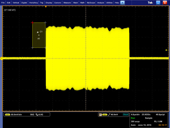
Here’s what the RF envelope of this pulse looks like on an 8GHz oscilloscope using a somewhat lousy coaxial cable:

A fair amount of ripple and some droop can be observed in the RF envelope, resulting from the lousy RF cable and the AWG’s output.
The Precompensation plug-in in the AWG can correct this response by automatically generating a set of precompensation filter coefficients, and then processing the waveform through this filter to “pre-distort” the waveform data. The resulting output at the end of the RF cable will then be corrected. To start, simply open the Precompensation tab in the user interface:

This plug-in generates a test signal which is measured on the oscilloscope, and it uses that measured result to generate the filter. The first thing to do is tell the AWG to “connect” to the oscilloscope. This is most often done through Ethernet using VISA. As long as the VISA server on the AWG can “see” the scope, it will show up on the drop-down “Instrument Connection” list. Next, configure the appropriate settings for the AWG Output and scope input channels. Select the RF Start Frequency, End Frequency and Frequency Resolution. It’s a good idea to set a start frequency that is fairly low – this will help to account for any possible reflections in a long coaxial cable. Set the end frequency to something higher than the maximum frequency content of your waveform. The frequency resolution should be a small fraction of your signal’s bandwidth. Next, enter a filename for the correction coefficients to be stored.
When you hit the “Create Coefficients” button, you’ll see a progress bar in the user interface while the AWG creates the test waveform, outputs it to the scope, and acquires it for analysis.

When the process of creating the filter coefficients is complete, a dialog box will display the amplitude and phase response of the correction filter:

The next step is to apply the corrections to the waveform. In the Waveform List, right-click on the waveform that you want to correct, and select the “Apply Correction” item in the pop-up menu:

Select the “Correction File Path” radio button, and use the folder icon to navigate to the correction filter file you just created. Select the “Create New Waveform” button, and hit Apply to create a pre-compensated version of your original waveform.

When you select the coefficients, a dialog box will show up to show you the filter’s characteristics:

In a few seconds, a new waveform (with “_corrected” appended) will appear in the Waveform List:

You can see the result of the precompensation on the waveform when you load it into a channel for playback:

And this is the result of sending the precompensated 1GHz bandwidth chirp to the scope:

The Precompensation process has measured the amplitude and phase response of the AWG and attached coaxial cable, built a filter to compensate for this response, and then pre-distorted the waveform so that the resulting output is flat.
Conclusion
This precompensation capability is applicable to all types of waveforms, not just wideband RF. These same corrections can be applied to pulsed waveforms, high speed serial data streams, and more. You can customize the frequency range that you’d like perform the corrections over to ensure that your signal is properly precompensated. The plug-in also allows you to apply a simple Gaussian filter to your signals, as well as simply compensating for the sinx/x rolloff of the sampled data.
To learn more, check out these links on tek.com:
- AWG70000 Series Waveform Generators
- SourceXpress Waveform Generation Software
- Precompensation Plug-in for SourceXpress
- DPO/MSO70000 Series Oscilloscopes from 4GHz to 33GHz
- Signal Generators