

Characterizing a metal’s resistivity requires you to measure very low resistances (and therefore, low voltages) accurately. Many techniques used for metals are applicable to other applications, such as the resistance of superconductors, nanowires, graphene (a one-atom –thick form of carbon), and other nanomaterials. All involve measuring small voltages in which the applied power must be kept low to prevent device self-heating.
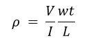
Figure 1 illustrates a system for determining the resistivity of a metal bar or rod. A current source is connected to both ends of the sample and voltmeter leads are places a known distance apart on its surface (L). The resistivity of conductive materials is typically found by sourcing a known current (I), measuring the voltage drop (V), then calculating the resistivity (ρ) from the measured voltage, the magnitude of the source current, the cross sectional area (A=wt), and the distance between the voltmeter leads, using this equation:

Common Errors
For conductive materials like metals, this voltage drop is usually just microvolts or nanovolts, so precise measurements are crucial. Potential error sources include test lead resistance, thermoelectric voltages, low frequency noise, external noise sources, Johnson noise, and the use of a voltmeter with insufficient sensitivity. Fortunately, special techniques can exist to reduce the impact of these errors. For example, using the four-wire method, in which one set of leads are used to source the current and another set are used to measure the voltage drop across the sample, will eliminate the effects of lead resistance.

Figure 1. Determining the resistivity of a metal bar or rod
Thermoelectric Voltages
Thermoelectric voltages are a common source of error when making low voltage and low resistance measurements. These voltages are generated when different metals in the circuit are at different temperatures. To reduce thermoelectric voltages, construct test circuits using the same materials for interconnects. Minimize temperature gradients within the test circuit and allow the test equipment to warm up and reach thermal equilibrium. Finally, use an offset compensation method to overcome these unwanted offsets, such as a current-reversal method or a delta mode offset compensation technique (see below).
Johnson Noise
The fundamental limit to measurement is Johnson noise in the source resistance. In any resistance, thermal energy produces motion of charged particles. This charge movement results in noise, which is often called Johnson or thermal noise. The power (P) available from this motion is given by:
P = 4kTB
where: k = Boltzmann’s constant (1.38 × 10⁻²³J/K)
T = absolute temperature in K
B = noise bandwidth in Hz
Metallic conductors approach this theoretical noise limit, while other materials produce somewhat higher noise. Johnson voltage noise (E) developed in a resistor (R) is:

and Johnson current noise (I) developed by a resistor (R) is:

All real voltage and current sources contain an internal resistance; therefore, they exhibit Johnson noise. Figure 2 shows Johnson noise voltage versus source resistance for various bandwidths (or rise times) at room temperature.

Figure 2: Noise Voltage vs. Bandwidth at Various Source Resistances
The previous equations suggest several means for reducing Johnson noise. It might be possible to reduce the bandwidth, the source temperature, or the source resistance.
Johnson noise also imposes a theoretical limit to achievable voltage or current resolution. This will affect the choice of instrument that is used to measure the low voltages required. As shown in Figure 3, Nanovoltmeters are the best instrument for measuring very low voltages that come close to the theoretical limits but only up to a specific device resistance.


Figure 3: Theoretical Limits of Voltage Measurement & Different Instruments with Different Noise Levels
Delta Mode Techniques
The delta mode is a technique for removing both constant thermal offsets and varying thermal offsets. The technique involves applying a current and measuring the voltage, then reversing the current and re-measuring the voltage two more times. The differences between the measurements and their average is the voltage response due only to the sample resulting from the applied current level. Repeating the process and using averaging reduces noise. Keithley’s Model 2182A Nanovoltmeter and Model 6220 or 6221 Current Sources automate these delta mode measurements and are appropriate for a wide range of resistivity.
Reducing External Noise
External noise sources are interferences created by other electrical equipment. They can be controlled by shielding and filtering or simply by eliminating the noise source. Because these noise sources are often at the power line frequency, avoid test frequencies that are exact multiples or fractions of the 50Hz or 60Hz. When using DC instruments and reversal methods, reducing external noise can be achieved simply by integrating each measurement for an integer number of power line cycles.
Conclusion
Measuring the resistivity of conductors can be challenging due to all of the potential sources of error, but the techniques detailed in this blog can significantly improve measurements results. Most digital multimeters can’t measure the microvolt or nanovolt level voltage drops accurately enough to produce a good measurement. It is necessary to have a very sensitive voltmeter, such as the Model 2182A Nanovoltmeter, which has 1nV resolution, to make proper measurements. It is also necessary to have an accurate current source, such as the Model 6220 or 6221 Current Source, to reduce errors in calculating the resistivity.
You can learn more about Delta Mode and other resistance measurements at this related blog: Low Resistance Measurement with a SourceMeter: Do I use Current Reversal, Offset Compensation or Delta Mode measurement methods?
For more information on the products discussed in this blog, click on the following links:
To learn more about Resistivity measurements, download the applications note: Measuring the Resistivity and Determining the Conductivity Type of Semiconductor Materials Using a Four-Point Collinear Probe and the Model 6221 DC and AC Current Source
To learn more about making accurate low level instruments, download the Low Level Measurements Handbook – 7th Edition