

This article is based on a presentation by Mary Anne Tupta, Senior Applications Engineer, Keithley Instruments, a Tektronix company, at the American Physical Society March 2021 Meeting.
Measuring resistivity accurately is crucial in research on devices and materials like superconductors, conductors, low power materials, semiconductors, and intrinsic semiconductors. Essentially, a sample’s resistivity is determined by measuring its resistance, then factoring in geometric considerations. Unlike the two-wire resistivity measurement method, which involves sourcing voltage and measuring current, the four-wire method requires sourcing current and measuring voltage.

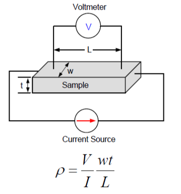
Figure 1. The four-wire technique for measuring volume resistivity of a bulk material, such as a superconductor. The current source (I) is connected to both ends of the sample through one pair of leads. The voltage drop (V) is measured using a second pair of leads spaced a known distance (L) apart. Using the equation shown, the resistivity (ρ) of the sample is calculated using the cross-sectional area (A=wt) and the distance between the voltmeter leads. Volume resistivity is expressed in ohm-cm.

Figure 2. Four-wire sheet resistance (σ) measurements are often used to characterize thin films, coatings, semiconductor layers, and metal deposition. Here, the thickness of the sample is negligible with respect to its area. The procedure is the same as for volume resistivity measurements. For a sample of uniform thickness, the sheet resistance is just the measured resistance multiplied by the sample width, divided by the length. It is typically expressed as ohms/square.
The magnitude of the measured resistance typically dictates the most appropriate type of instrumentation and the techniques needed to achieve the optimal results. Table 1 lists some approximate ranges of measured resistances and corresponding example applications.
Table 1.
|
Resistance |
Applications |
|
Conductors (<100mΩ) |
Metals, superconductors, conductive oxides, heavily doped substrates (Often made with a separate current source and nanovoltmeter) |
|
Low Power Measurements (<10mV, <10µA) |
Nano-materials, nano-wires, graphene (Often made with a combination of a current source and a nanovoltmeter, an SMU/Keithley SourceMeter® instrument, or a parameter analyzer with multiple SMUs built in) |
|
Mid-range Measurements (10Ω to 1kΩ) |
Semiconductors, doped semiconductor wafers, anti-static materials, indium tin oxide (ITO), coatings (Using a separate current source and voltmeter or a SourceMeter/SMU with a four-point probe) |
|
High Resistance Measurements (>10MΩ) |
Intrinsic semiconductors, diamonds (Often requiring the use of an electrometer) |
In addition to choosing the right instrumentation, be prepared to deal with these potential sources of error in resistance and resistivity measurements:
- Test lead and contact resistances: Always use four-wire measurements.
- Thermoelectric voltages (VEMF): Error voltages are generated when dissimilar metals in the circuit are at different temperatures. Allow the instrumentation to warm up before making measurements and use the current reversal method (measuring voltage twice with currents of opposite polarity, then averaging the two readings) to cancel the offset.
- External noise sources: Remove the noise source, filter out the noise, or shield the circuit.
- Johnson Noise: Reduce the temperature, bandwidth, or sample resistance.
To learn more, consult Keithley’s collection of application notes, including the 7th edition of our Low Level Measurements Handbook, all available at http://www.tek.com/resistivity.